Putting your skills to use.
So far in this level you have been learning the basic 2D AutoCAD commands. What you learned in this level will be a very large part of what you use in your daily drafting. This tutorial isn't going to teach commands, but will instead show a common technique that is used a lot in 'Mechanical" drafting. It will also ask you to think about what you are drawing, and how it needs to be represented.
Mechanical drafting is a field within the drafting world. In simple terms, it is used to describe the methods for drafting and designing machines, assemblies and in a nut shell, the 'parts' that used in everything from a fork to a Formula 1 race car. It doesn't include anything that involves buildings and structures (Architectural & Structural drafting) or landscapes and roads (Civil drafting and engineering).
Now just because you are dreaming of becoming an Architect, it doesn't mean that you should skip this tutorial. In fact, you will likely need to use these concepts or read diagrams related to this subject. So read on!
What is Orthographic Projection?
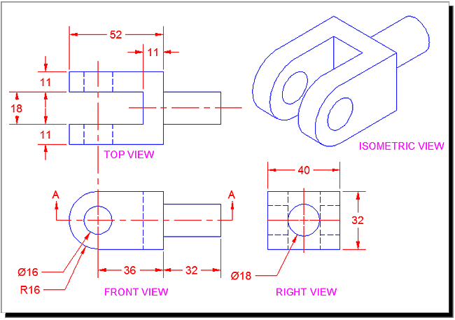
If you look at the image below, you will see a drawing for a part. It shows the object with a top view, a front view and a side view. You'll also see an Isometric view that is sometimes used to give a more visual look. This tutorial won't cover Isometric drafting as it is shown in Tutorial 3-2. Save your drawings that you do in this exercise for more practice in that lesson.
The reason that this method is used is that you can take a designed part, draw it, dimension it and then give all the needed information to the manufacturer.
In some cases only 2 views are needed, but for anything more than a simple part, 3 or more views are needed. Very complex parts will need 6 or more.
There are 2 methods of deciding what views are used and where they are placed in the drawing. I'll borrow some info from Wikipedia to show this:
First-angle projection (European Standards)
In first-angle projection, the object is conceptually located in quadrant I, i.e. it floats above and before the viewing planes, the planes are opaque, and each view is pushed through the object onto the plane furthest from it. (Mnemonic: an "actor on a stage".) Extending to the 6-sided box, each view of the object is projected in the direction (sense) of sight of the object, onto the (opaque) interior walls of the box; that is, each view of the object is drawn on the opposite side of the box. A two-dimensional representation of the object is then created by "unfolding" the box, to view all of the interior walls. This produces two plans and four elevations. A simpler way to visualize this is to place the object on top of an upside-down bowl. Sliding the object down the right edge of the bowl reveals the right side view.
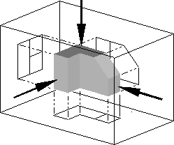 | 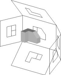 |
Image of object in box, with views of object projected in the direction of sight onto walls using first-angle projection.
|
Similar image showing the box unfolding from around the object.
|
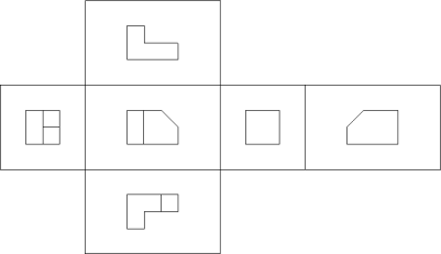 |
Image showing orthographic views located relative to each other in accordance with first-angle projection.
|
Third-angle projection (USA Standards)
In third-angle projection, the object is conceptually located in quadrant III, i.e. it lurks below and behind the viewing planes, the planes are transparent, and each view is pulled onto the plane closest to it. (Mnemonic: a "shark in a tank", esp. that is sunken into the floor.) Using the 6-sided viewing box, each view of the object is projected opposite to the direction (sense) of sight, onto the (transparent) exterior walls of the box; that is, each view of the object is drawn on the same side of the box. The box is then unfolded to view all of its exterior walls. A simpler way to visualize this is to place the object in the bottom of a bowl. Sliding the object up the right edge of the bowl reveals the right side view.
Here is the construction of third angle projections of the same object as above. Note that the individual views are the same, just arranged differently.
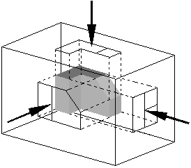 | 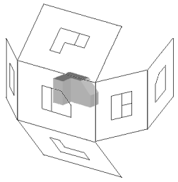 |
Image of object in box, with views of object projected in the direction of sight onto walls using first-angle projection.
|
Similar image showing the box unfolding from around the object.
|
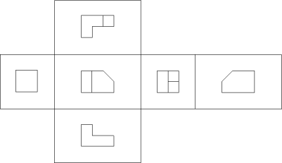 |
Image showing orthographic views located relative to each other in accordance with third-angle projection.
|
|
Ok - that was some fun theory - thank for reading it. One last bit of info before we get back to CAD stuff. Since there are 2 kinds of standards, how do you know which is which when you have a drawing in front of you? There is a standard symbol that is used in the title block to indicate which method was used.
This symbol shows a simple cone and displays the projection. Think about which symbol represents which method, then move your mouse over the images to see if you were correct.
Because I am in North America and was trained to use the "Third Angle Projection" method, that is what I will show in this tutorial. The techniques for drawing are the same, it's just a matter of which direction you 'project' or draw the lines.
Here's a short video for you that explains these concept visually.
Drawing 3 View Orthographic Projection
For these exercises, we'll start by looking at an Isometric drawing of an object and then draw the Front, Side and Top views using the dimensions we're given. In the workplace, you might find that you are given a part to measure and then draw, or you might be designing the part yourself.
Here's the part that we'll draw in this tutorial:
This is a very simple example to get you used to the concepts. You'll have more practice exercises at the bottom.
Ok, the first question that you'll ask yourself, is "Where do I start?". I recommend that you start where you have the most information. This will sometimes be the front or the top - it depends upon each drawing. In this case, I will start with the front and draw it.
You don't need to worry about dimensioning it at this point - wait until you have all of your views drawn. Ok, this should have been easy enough, so now you can start drawing the top view.
To draw the top, you need to 'project' the lines up. Draw lines up from the main points in your front view. Make sure you have your Osnaps on (include "Quadrant").
Now that you have the vertical lines, draw the horizontal lines. Make sure you leave enough room to draw the width (via OFFSET) and space between the views.
Now you almost have 2 views drawn. Trim the lines so that you are left with just the lines you need.
Stop and check to make sure that you didn't forget any lines. It's very easy to miss some.
Now it's time to jump ahead a little and take a side trip. Read Tutorials 4-3 to learn about Linetypes, because you will need them here. After reading the tutorial, return to your drawing and load the Hidden and Center linetypes. These are needed to add more information in your drawing.
If all went well, you should be able to load the linetypes and scale them (LTS with a value of 10 or 12) to fit with your drawing.
What you see above is the completed Top and Front views. Do you understand why there are "Hidden" lines? They are there to indicate that the hole (circle) is drilled right through the block. Where would the lines be in the hole was only drilled half way through? The center lines are used to show the the hole and the arc have the same center point. These are both common and standard CAD methods and you need to understand them.

One more view to draw. This will be the side/right view. Can you picture it yet?
To get started on the side view, you have to establish where it will be placed in the drawing. In this example and using the 3rd Angle projection, it will be shown to the right of the front view. For exact placement, you need to draw more projection lines.
What you see in the image above is that I established the top right corner of my front view by projecting 2 lines. Then I drew a 45 degree line up from the corner.
Now I can start projecting lines from my top view to create the side view. The line that is indicated by the 'Project Down' leader will be the left side of my Right Side View. I would project another from the other side of the top view and that would establish the width of the right side. Also note that by using this technique the top and side views are the same distance from the front view.
From there I just need to project to the right from my front view.
Almost there. Now you just need to trim up some lines and change the linetype for the hidden lines. Final goal is to draw this:
Once you have all of your lines, your center lines and your hidden lines, you are ready to dimension and add any notes that are needed.
Think about what commands you used in this tutorial. You used LINE, CIRCLE, OFFSET & TRIM. You also use Layers and then learned about Linetypes. What this shows is that you don't need to use a lot of commands, but it's your knowledge of how those commands works that makes your reputation as a CAD user.
Extra Practice: Draw the missing Right Side View and the other views (except Isometric) for this drawing.
Extra Practice: Here is a scan from an old (1919) drafting book that I found on Google Books. This image has 4 separate exercise to keep you busy. Draw what you are given, and then draw the missing view.
Extra Practice: Draw the 3 views needed for each of these blocks. Extra 1 - Extra 2
Just one more thing I should mention. This method of drafting can be used in other ways as well.
To the right is a simple piece of duct work drawn in AutoCAD. It's a straight piece that has been cut at an angle so that it can be connected to another piece to form a bend.
Drawing in 3D isn't very hard when you know how. But if I sent this to the manufacturer, he wouldn't really know where to start. So I would have to send him a drawing of the tube rolled out.
This would give him a template to cut the shape and manufacture the part.
Think about what this shape would look like if it was flat. How would you draw it? How would get the curve correct? Do you think that this sounds like a job for Orthographic Projection?
Yes it does.
The drawing below shows how this could be drawn to show all aspects of this part. I have the diameter of the pipe and the length to the top and the length to the bottom. Since I have the diameter, I also have the circumference. The circumference tells me the length of material that will be needed to make the piece.
The part is drawn in Magenta, and the projection lines are in Blue. What I needed to do was use the DIVIDE command to divide both the circle and the line that represents the circumference. Then it was a matter of projecting down and to the right from the circle, and up from the circumference line. This gave me a grid to use for the SPLINE to create the curve. The Auxiliary view was drawn with a few projection lines and an ELLIPSE.
Try this if you like and follow the command line for the commands you don't know. This might be tough, but take your time.
|  |

Here's a video that shows how to construct a basic Orthographic Projection drawing.
Source From:www.mycadsite.com
|